Tuesday, 31 January 2023

Waterfurnace TP32U03 Programmable Thermostat User Guide

WATERFURNACE-logo

Waterfurnace TP32U03 Programmable Thermostat 

Waterfurnace-TP32U03-Programmable-Thermostat-User-Guide-product-removebg-preview

THERMOSTAT OPERATION

ADJUSTING TEMPERATURE (Temporary Override in Programmable models)

  1. Before you can adjust the temperature, a MODE must be selected. If you are already in Heating or Cooling mode, then skip stepping 5.
  2. To select a MODE, use the keypad arrows to scroll to MODE, and then press the center button on the keypad to enter the operating mode menu. OUTDOORWaterfurnace-TP32U03-Programmable-Thermostat-User-Guide-product-fig-2
  3. Select the desired mode by scrolling up or down, with the arrows, and then press the center button on the keypad to enter into that mode. You are now returned to the Main Menu and Figure 1 is a similar view. NOTE: Outdoor temperature is only displayed if an outdoor sensor is installed.
  4. To increase the temperature set point, use the arrow up button. To decrease the set point, use the arrow down button. Press the center button on the keypad for the new set point to be effective

SETTING DATE AND TIME

  1. From the Main Menu, scroll to MENU and press the center button ■ on the keypad.
  2. Select SET DATE AND TIME
  3. If your area observes daylight savings time, select AUTO DAYLIGHT SAVING, scroll to ON, then press the center button ■ to save. You will be returned to the select SET DATE AND TIME menu. Scroll to SET DATE AND TIME and press the center button ■ on the keypad.
  4. SET MONTH by using the up and down arrows ▲▼, and then press the center button on the keypad to save the month.
  5. SET DAY by using the up and down arrows ▲▼, and then press the center button on the keypad to save the day.
  6. SET YEAR by using the up and down arrows ▲▼, and then press the center button on the keypad to save the year.
  7. SET HOUR by using the up and down arrows ▲▼, and then press the center button on the keypad to save the hour.
  8. SET MINUTE by using the up and down arrows ▲▼, and then press the center button ■ on the keypad to save the minute.
  9. The date and time are now set. You can return to the Main Menu by pressing the left arrow key to return to the previous menu.

HOLD SETTING — Vacation & Permanent (Programmable models only) This section describes the HOLD functions. You can program the thermostat to hold the temperature for a period of time. If you want to hold the temperature for a few hours or a few weeks, your thermostat can accommodate your schedule.

VACATION HOLD (Programmable models only)

  1. From the Main Menu, scroll to MENU and press the center button ■ on the keypad.
  2. Select HOLD → VACATION
  3. First, the thermostat prompts you for a temperature to hold. If you are in AUTO MODE you will be prompted for both a heat setting and a cool setting. Use the up and down arrow keys ▲▼ to select the desired temperature and press the center button on the keypad.
  4. Next, it will prompt you for a date and time that you wish to return to the programmed operation. Returning to the Main Screen, you will notice that in the upper part of the screen is alternating HOLD TIL *date and time you specified* and the actual date and time.
  5. To cancel this hold, scroll to CANCEL HOLD from the Main Menu and press the center button ■.

PERMANENT HOLD (Programmable models only)

  1. From the Main Menu, scroll to MENU and press the center button ■ on the keypad.
  2. Select HOLD → PERMANENT
  3. First, the thermostat prompts you for a temperature to hold. If you are in AUTO MODE you will be prompted for both a heat setting and a cool setting. Use the up and down arrow keys ▲▼ to select the desired temperature and press the center button on the keypad.
  4. Returning to the Main Screen, you will notice that in the upper part of the screen is alternating PERMANENT HOLD and the actual date and time.
  5. You can adjust to the permanent hold temperature at will, and the temperature you select will remain until the permanent hold is canceled.
  6. To cancel this hold, scroll to CANCEL HOLD from the Main Menu and press the center button ■. This will revert to the programmed settings.

FAN OPERATION The thermostat can operate the fan in four ways:  AUTO (on only during heating and cooling calls) ON (always on)

INTERMITTENT (cycles fan) Pg. 3
PROGRAMMED FAN (fan follows the program set in the program menu screen) (programmable models only) Pg. 3

  1. From the Main Menu, scroll to (FAN) and press the center button on the keypad ■.
  2. Select the operation you desire as described above.

CHANGING MODES

  1. From the main screen select MODE.
    Select the operating mode you need and press the center button ■.
    NOTE: If selecting EMERGENCY HEAT, the backlight color will change from blue to red indicating that auxiliary heat is operating instead of the heat pump compressor. Auxiliary/emergency ⊲ PREVIOUS
    heat is significantly more expensive to operate than the heat pump compressor, and should not be selected unless the heat pump compressor is not operational.

FAHRENHEIT OR CELSIUS Waterfurnace-TP32U03-Programmable-Thermostat-User-Guide-product-fig-5

  1. 1. From the Main Menu, scroll to MENU and press the center button ■ on the keypad.
    2. Select SETINGS → SCREEN SETTINGS → FAHRENHEIT OR CELSIUS
    3. Select which scale you prefer.

FAHRENHEIT OR CELSIUS

  1. From the Main Menu, scroll to MENU and press the center button ■ on the keypad.
  2. Select SETINGS → SCREEN SETTINGS → FAHRENHEIT OR CELSIUS
  3. Select which scale you prefer.

12 OR 24-HOUR CLOCK
Within this menu option, you can change the time displayed by your thermostat to 24 Hour time (Military Time).

  1. From the Main Menu, scroll to MENU and press the center button ■ the keypad.
  2. elect SETINGS → SCREEN SETTINGS → 12 OR 24 HOUR CLOCK
  3. elect which time base you prefer.

CONTRAST ADJUSTMENT
You can change the contrast level of your thermostat screen to be displayed your preference.

  1. From the Main Menu, scroll to MENU and press the center button on the keypad.
  2. elect SETINGS → SCREEN SETTINGS →CONTRAST
  3. use the up and down arrows ▲▼ to increase or decrease the contrast level.
  4. Press the center button to accept the new setting.

BACKLIGHT ON TIME
This thermostat has a two-color backlight feature. Anytime a button is pressed, the blue backlight stays on for a certain amount of time. A red backlight is visible if you are selecting Emergency Heat mode. You can adjust the amount of time the backlight stays on in the menu options.

  1. From the Main Menu, scroll to MENU and press the center button ■ on the keypad.
  2. Select SETINGS → SCREEN SETTINGS →BACKLIGHT ON TIME
  3. You can change the backlight on time by using the up and down arrows ▲▼. 30, 60, 90, 120, and ON (all the time) are your choices. Press the center button to save the new backlight on time.

PROGRAMMING YOUR THERMOSTAT (programmable models only)
PRESET PROGRAMMING
Preset options will step you through the programming. Simply select the temperatures and then view the completed program.

PROGRAMMING A DAY OR A SERIES OF DAYS

After selecting the programming screen, you have the option of programming every day, weekdays, weekends, or individual days. Once you’ve selected a certain day to program, a screen appears that allows you to set the time, heat setting, cool setting, and fan operation for each event.

  1. From the Main Menu, scroll to MENU and press the center button ■ on the keypad. Waterfurnace-TP32U03-Programmable-Thermostat-User-Guide-product-fig-6
  2. Select PROGRAM
    You can program each day differently by going through each day and personalizing them. Or, you can program every day the same by scrolling to every day. Or, you can program the weekdays or weekends the same by selecting the appropriate menu item.
  3. You can program each day differently by going through each day and personalizing them. Or, you can program every day the same by scrolling to every day. Or, you can program the weekdays or weekends the same by selecting the appropriate menu item.
  4. To program every day the same, select every day and then press the center button ■.Waterfurnace-TP32U03-Programmable-Thermostat-User-Guide-product-fig-7
  5. Using the right arrow button ►, highlight the WAKE time, and change to desired time by using the up and down arrow ▲▼ buttons. Move to the next entry by using the right arrow button ►. To change the HEAT set point, use the up and down arrows. Continue this process until all settings are to your liking.
  6. To save these settings, scroll to SAVE, and press the center button ■.In the PROGRAM menu, there is an option to COPY. The option can be used to copy the program from one day to another day. After COPY is selected, the thermostat will prompt you for which day to copy from. Next, it will prompt you for which day to copy the program. After these selections, it will then confirm what is being copied to where. At this point, you have the option of canceling the copy process, by pressing to return to the copy menu, or saving what you have by pressing the center button ■. The SAVED screen will appear returning you to the copy menu. Pressing ◄ will return you to the PROGRAM menu. Pressing ◄ again will return you to the MAIN MENU.

ADVANCED SETTINGS

SECURITY LOCKOUT
This thermostat has the option to set security features to lock out everything but the adjustment of the temperature or a total keypad lockout.Waterfurnace-TP32U03-Programmable-Thermostat-User-Guide-product-fig-8

  1. From the Main Menu, scroll to MENU and press the center button ■ on the keypad.
  2. Select SECURITY LOCKOUT.
  3. Select whether you want to lock out everything but TEMP ADJUST ONLY or TOTAL KEYPAD LOCKOUT.
  4. Either selection will bring you to the Enter Pin Number screen.Waterfurnace-TP32U03-Programmable-Thermostat-User-Guide-product-fig-9
  5. Using the up and down arrows ▲▼, select a pin number to lock out the thermostat. The right arrow ► moves you to the next pin digit.
  6.  Once you’ve entered the 4-digit pin number, press the center button ■ to save the pin. The screen will display LOCKED and return to the main Screen.
  7. Once you return to the Main Screen, in the upper left of the screen will alternate between LOCKED and the date and time.
  8. If you selected TEMP ADJUST ONLY, you will only be able to adjust the set point temperature. Any other operation will require the pin number to unlock the thermostat.
  9. Once unlocked, you’ll have to set a pin number again to lock out the thermostat again.
  10. In the event, the pin number is lost default is 9999

OFFSETS

MENU → SETTINGS → OFFSETS
TEMPERATURE OFFSETS
This option allows calibration (or deliberate miscalibration) of the room temperature sensor(s). There are various reasons why the displayed temperature would be adjusted to a higher or lower value. NOTE: Do not adjust for 30 minutes after installation because the board may be heated by handling. The selected number is the number of degrees, plus or minus, which will be added to the actual temperature. The numbers can range between -5° and +5°. Default values are set to 0° offset.

Temperature Offset
Remote Indoor Offset (if the sensor is attached) Outdoor Offset (if the sensor is attached)

HUMIDITY OFFSET
This option allows the calibration of the humidity sensor. Adjustments can range between -10% and +10%. The default is 0% offset.

AUTO CHANGEOVER
With the auto changeover, the thermostat automatically switches itself from heating to cooling, or vice versa, based on the setpoints. When setting up the thermostat you have to enter both a cooling setpoint and a heating setpoint. The thermostat will also prevent the user from setting the cooling setpoint lower than the heating setpoint. The mode is set to AUTO for this operation to work.

MENU → SETTINGS → AUTO CHANGEOVER
Auto Changeover Time – This setting sets the minimum off time before the thermostat can change from one mode to another. The default is 5 minutes. The range is from 0-120 minutes in 15-minute increments.
Auto or Manual Change – Default is AUTO. If MANUAL is chosen, you will need to change from heating to cooling or vice versa. When MANUAL is set, AUTO is removed from the MODE screen as a choice.

INTERMITTENT FAN
Temperature conditions can vary widely between the thermostat location and extremities of the space the thermostat serves. This air stratification problem can be especially pronounced during mild outdoor conditions when long periods elapse between space conditioning demands from the thermostat. This intermittent fan operation can also improve the performance of air cleaning or special filtration systems that locate the cleaning or filtration media at the return air side of the fan.

  1. MENU → SETTINGS → INTERMITTENT FANWaterfurnace-TP32U03-Programmable-Thermostat-User-Guide-product-fig-10
  2. If the FAN hasn’t been on for an hour, the fan will start cycling based on these times. The default is OFF. The first screen is the amount of time you want the fan to be energized. Ranges are OFF, or 5-20 minutes in 5-minute increments.Waterfurnace-TP32U03-Programmable-Thermostat-User-Guide-product-fig-11
  3. After entering this time and pressing the center button ■, the next screen is the amount of time the fan is OFF. Ranges are 0 minutes or 5-40 minutes in 5-minute increments.
  4. After entering this time and pressing the center button ■ you will be returned to the Setting Menu screen.Waterfurnace-TP32U03-Programmable-Thermostat-User-Guide-product-fig-12
  5.  Fan ON and OFF cycles will continue until the fan has been energized by a call for heating or cooling.

SERVICE INFORMATION
MENU → SETTINGS → SERVICE INFO
These screens help an installer or contractor to have a good understanding of what problems might be occurring before arriving for service.

WARNING: Before installing the thermostat, turn off all power to the unit. There may be more than one power disconnect. Electrical shock can cause personal injury or death.

INSTALLER

INFORMATION / ADVANCED FEATURES
SAFETY CONSIDERATIONS
Improper wiring or installation may damage a thermostat. Wiring must conform to local and national electrical codes

INTRODUCTION
The thermostat is a wall-mounted, low-voltage thermostat that maintains room temperature by controlling the operation of a heating and air conditioning system. Batteries are not required; temperature and mode settings are preserved with the power off.

INSTALLATION CONSIDERATIONS
The thermostat requires no batteries. The thermostat is not a power-stealing device and MUST have both R and C connected.

INSTALLATION

THERMOSTAT LOCATION
The thermostat should be mounted:

  • Approximately 5 ft. (1.5m) from the floor.
  • Close to or in a frequently used room, preferably inside On a section of wall without pipes or ductwork.
    The thermostat should NOT be mounted:
    • Close to a window, on an outside wall, or next to a door leading to the outside.
    • Exposed to direct light and heat from a lamp, sun, fireplace, or another temperature-radiating object which may cause a false reading.
    • Close to or in direct airflow from supply registers and return-air grilles.
    • In areas with poor air circulation, such as behind a door or in an alcove.

INSTALL THERMOSTAT

  1. Turn off all power to the unit.
  2. If an existing thermostat is being replaced:
    •  Remove the existing thermostat from the wall.
    • Disconnect wires from the existing thermostat, one at a time. Be careful not to allow wires to fall back into the wall.
    • As each wire is disconnected, record the wire color and terminal marking.
    • Discard or recycle old thermostats.
    • NOTE: Mercury is a hazardous waste and MUST be disposed of properly.
  3. Separate the front and back pieces of plastic.
  4. Route thermostat wires through holes in the back piece of plastic. Level plastic against the wall (for aesthetic value only – thermostat need not be leveled for proper operation) and mark the wall through 2 mounting holes.
  5. Drill two 3/16-in. mounting holes in the wall where marked. (Note: Mounting holes on the thermostat are designed to fit on a horizontal J-box).
  6. secure the back plastic to the wall with 2 anchors and screws provided making sure all wires extend through the hole in the plastic.
  7. Connect wires to the proper terminal of the connector block in the front plastic.
  8. Push any excess wire back into the wall. The excess wire inside the thermostat plastic case can interfere with proper airflow across the temperature sensor. Seal the hole in the wall to prevent air leaks. Leaks can affect operations.
  9. Snap front and back pieces of plastic together.
  10. Turn on the power to the unit
WIRING DIAGRAMS
All excess wire should be pushed back into the wall as far as possible. The excess wire inside the thermostat plastic case may interfere with the airflow across the temperature sensor.

THERMOSTAT CONNECTIONS

  • C – 24V Common for Control Circuit
  • R – 24V Supply for Control Circuit
  • W1 – Auxiliary Heat
  • W2 – Not Used
  • H – Humidifier (When used)
  • DH – Dehumidifier (When used)
  • O – Reversing Valve – energized in COOL mode Y2 – 2nd Stage Compressor / Cooling / Heating Y1 – 1st Stage Compressor / Cooling / Heating G – Fan
  • L – Alarm Input
  • V – Not Used
  • A+, B – Not Used
  • GND – Ground
  • OD – Outdoor Temperature Sensor
  • ID – Indoor Temperature SensorWaterfurnace-TP32U03-Programmable-Thermostat-User-Guide-product-fig-13

The dashed line represents 2 Stage Heat Cool Connections and optional “L” terminal connection for Control Board & Comfort Alert faults

INSTALLER SETTINGS

NOTE: These options are intended to be used by the installer. End users are not advised to change or modify any of these settings. Doing so may make your equipment stop working properly and/or may void the warranty of the thermostat as well as the equipment hooked up to the thermostat. To access the installer setting menu, the mode must be set to OFF. Then, press both the up and down arrow keys at the same time for at least 5 seconds to enter the installer screen.

MODEL CONFIGURATION
Options to select from:

PROGRAMMABLE / NONPROGRAMMABLE, SINGLE-STAGE/MULTI-STAGE

  • Single Stage – Used with heat pumps with PSC motors
  • Multi-Stage – Used with heat pumps with ECM motors, either Single Speed or Dual Capacity

NORMAL/DUAL FUEL/INTELLIZONE STANDARD/ INTELLIZONE NO DOWN STAGING

  • Normal – used for normal operation
  • Dual Fuel – used on dual fuel systems Needs outdoor sensor to lockout dual fuel.
  • Intellizone Standard – used with Intellizone. The ‘W’ acts like a Y3 and requires less droop. It activates 3rd stage with the same
    time/temperature weighting as Y1 and Y2.
  • Intelligence No Down Staging – used with Intellizone and if used, SHOULD BE ONLY ON MAIN ZONE. The thermostat will hold the deepest call encountered and should minimize compressor speed changes.

ACCESSORIES
Each of these options has settings for Cumulative Run Time and Calendar Time. Messages will flash at the top of the Main screen when these events are met to alert the owner that it is time to service these options.

  • Air Filter – Cumulative Run Time default is 1000 hours and Calendar Time is 6 months. Values can range from 400-3600 hours for Cumulative Run Time (in 100-hour increments), or Calendar Time can be set to OFF, or 3-48 months (in 3-month increments).
  • Humidifier – Cumulative Run Time default is 0 hours (OFF) and Calendar Time is OFF. Values can range from 400-3600 hours for Cumulative Run Time (in 100-hour increments), or Calendar Time can be set to OFF, or 3-24 months (in 3-month increments).
  • UV Lamp – Cumulative Run Time default is 0 hours (OFF) and Calendar Time is OFF. Values can range from 400-3600 hours for Cumulative Run Time (in 100-hour increments), or Calendar Time can be set to OFF, or 3-48 months (in 3-month increments).
  • Air Cleaner – Cumulative Run Time default is 0 hours (OFF) and Calendar Time is OFF. Values can range from 400-3600 hours for Cumulative Run Time (in 100-hour increments), or Calendar Time can be set to OFF, or 3-24 months (in 3-month increments).
  • To cancel the message, select the CANCEL ALARM, and press the center button ■.

INPUT DEALER INFO
Contractors are able to input Brand Name, Model Number, Contractor Name, and Contractor Phone number into these screens. This way, the owner could give this information to the contractor so that he would know what system the owner has prior to the service visit.

Waterfurnace-TP32U03-Programmable-Thermostat-User-Guide-product-fig-14

  1. Scroll to the info you want to enter and press the center button ■.
  2. Enter the information by scrolling through the characters using the up & down arrows ▲▼. Once the character you want is set, press the right arrow ► to move to the next space and begin entering another character.
  3. Once you’ve completed filling out the field, press the center button ■ to save the entry and return to the INPUT DEALER INFO screen. Repeat this process for all fields you want to be saved.
  4. Once all fields have been entered, scroll to SAVE and press the center button ■.

FAN WITH HEAT OPTION

Options are ON or OFF. This selection determines whether G (fan) output is to be ON or OFF when W (auxiliary heat) output is ON.

HUMIDITY OPTION TP32U04 only.
If your system is set up with a humidifier, or you desire a dehumidification option, select the appropriate setting.

HUMIDIFY (TP32U04 only)
DEHUMIDIFY (TP32U04 only)
BOTH (H or DH)
NONE
To adjust the Set Point for Humidification or Dehumidification, Select the RH from the Main menu. The values can be selected and adjusted from that screen.
NOTE: If you have an outdoor sensor attached to the thermostat, the Humidification setting is adjusted automatically based on the outdoor temperature.
HUMIDIFY – Turns on the H output when the room humidity is below the set point and MODE is set to HEAT, EHEAT, or AUTO when Heating was the last mode run.
DEHUMIDIFY – Turns on the DH output when the room humidity is above the set point and the MODE is set to COOL or AUTO when Cool was the last mode run.
BOTH – HUMIDIFY operates in the HEAT mode and DEHUMIDIFY operates in COOL mode.
NONE – Neither is active.

REVERSING VALVE OPTION
Option of the reversing valve (O output) being on when in cooling or heating. The default is COOLING.

RESTORE DEFAULTS
This will allow you to revert to the factory default settings.

ANTICIPATOR
This adjustment controls the sensitivity and cycle rate of the thermostat. Higher numbers decrease the cycle rate. Lower numbers increase the cycle rate. The default value is 0, and the range is 0-4.

DIFFERENTIAL
This adjustment will vary the number of degrees, from the set point, before a call for heating or cooling is made. Adjustments can range between 0.5° and 4° differential. The default is 0.5° offset. (If your set point is 70°F in heating, your thermostat will not call for heat until the temperature is 69.5°F, with a 0.5 differential).

CYCLES PER HOUR
This feature will not allow more than the specified number of equipment cycles per hour. Values can range from 4 or 6 (or 1 cycle every 15 minutes (default) or 1 cycle every 10 minutes, if 6 is set). The factory default setting is 4. This default selection will provide optimum performance in nearly all installations.

MENU → SETTINGS → CYCLES PER HOUR
PROGRAM SETTINGS

  1. MENU → SETTINGS → PROGRAM SETTINGS

SMART RECOVERY
Smart recovery is a feature of your thermostat designed to improve comfort by adjusting temperatures to achieve a room temperature by the programmed time. When it’s time for a programmed
temperature change, smart recovery begins working in advance, turning the system on and off as needed to adjust the indoor temperature. During these transition periods, you may notice that the actual temperature and your temperature setting don’t match. That’s a smart recovery in action, adjusting temperatures in small increments for greater energy efficiency. This is more energy efficient than simply allowing the system to operate at full capacity until the desired temperature has been met. Smart Recovery helps avoid excessive use of auxiliary heat when recovering from night setbacks in the heating mode.

EVENTS PER DAY

Waterfurnace-TP32U03-Programmable-Thermostat-User-Guide-product-fig-15
This is where you can set the number of events per day. (An event is a period of time scheduled with a certain heating and cooling setpoint.) For instance, if you are away from your home from 8 am to 5 pm, make this period of time an event and set the thermostat at an energy-saving setting. You have the option of setting the events per day to 4-RESIDENTIAL (4 events), 2-RESIDENTIAL (2 events) or 2-BUSINESS (2 events).

Waterfurnace-TP32U03-Programmable-Thermostat-User-Guide-product-fig-16

SMART HEAT STAGING (HEAT PUMP ONLY)
This delays 3rd stage heating for a set time. Options are ON or OFF. The default is OFF. The range for this is 0-120 minutes in 5-minute increments. If set to ON, 30 minutes is the default time.( If ‘ON’ is selected and the demand has not been satisfied the thermostat will energize electric heat after the selected time has expired regardless of demand.)

COOLING LOCKOUT
When an outdoor temperature sensor is installed, it can be set up so the cooling option doesn’t energize if the outdoor temperature is below a certain temperature. Ranges for this are NONE (default), 45°F, 50°F, or 55°F.

ELECTRIC HEAT or Dual Fuel LOCKOUT
When an outdoor temperature sensor is installed, you can set it up so the electric heat or Dual Fuel option doesn’t energize if the outdoor temperature is above a certain temperature. Ranges for this are NONE (default), 5°F to 60°F in 5° increments.

COMPRESSOR SATISFY
Normal – allows compressor downstaging from Y2 to Y1. Recommended setting for Envision series products.
Y2 Finish – Once the heat pump has engaged Y2 the thermostat will not allow downstaging to Y1. The call is satisfied in Y2.

REMOTE SENSOR
Allows selection of the remote sensor to determine indoor temperature. Options are REMOTE SENSOR, AVERAGE, and STAND ALONE. The REMOTE SENSOR is connected to the ID and GND on the thermostat terminals.

REFERENCE:

Download Manual:

Waterfurnace TP32U03 Programmable Thermostat User Guide

WATERFURNACE-logo

Waterfurnace TP32U03 Programmable Thermostat User Guide

The post Waterfurnace TP32U03 Programmable Thermostat User Guide appeared first on thermostat.guide.


source https://thermostat.guide/waterfurnace/waterfurnace-tp32u03-programmable-thermostat-user-guide/

Venstar T1045 Programmable Thermostat Installation Instructuion

Venstar logo

Venstar T1045 Programmable Thermostat

Venstar T1045 Programmable Thermostat

Safety Warnings

CAUTION Follow Installation Instructions carefully.
DISCONNECT POWER TO THE HEATER – AIR CONDITIONER BEFORE REMOVING THE OLD THERMOSTAT AND INSTALLING THE NEW THERMOSTAT.

CAUTION
The two Alkaline “AA” batteries must be replaced at least once every 12 months to ensure proper operation. The Low Battery icon (fig. 1) will appear on the display when it is time to replace the batteries. If the thermostat is connected to 24v power, the batteries should still be installed, but are not required.

Venstar T1045 Programmable Thermostat fig-9When battry is displayed the batteries must be replaced immediately. The manufacturer cannot be liable for improper operation of the thermostat if the batteries are not immediately replaced.
Annual battery replacement is especially critical in locations subject to freezing temperatures. The thermostat will be unable to turn on the heating system if the batteries are exhausted.

Preparation

  • Proper installation of the thermostat will be accomplished by following these step-by-step instructions. If you are unsure about any of these steps, call a qualified technician for assistance.
  • These tools will be required:Venstar T1045 Programmable Thermostat fig-1
  • Make sure your Heater/Air Conditioner is working properly before beginning the installation of the thermostat.
  • Carefully unpack the thermostat. Save the screws and instructions.
  • Turn off the power to the Heating/Air Conditioning system at the main fuse panel. Most residential systems have a separate breaker for disconnecting power to the furnace.

Remove & Replace Old Thermostat

  • Remove the cover of the old thermostat. If it does not come off easily check for screws.
  • Loosen the screws holding the thermostat base or subbase to the wall, and lift away.
  • Disconnect the wires from the old thermostat. Tape the ends of the wires as you disconnect them, and mark them with the letter of the terminal for easy reconnection to the new thermostat.
  • Keep the old thermostat for reference purposes, until your new thermostat is functioning properly.

Battery Replacement

  1. The batteries are easily accessible from the battery slot located on the front of the thermostat (fig. 1). To open the battery slot, press down on the battery cover
    (fig. 1) and pull out (fig. 2).
  2. Remove the old batteries and replace with the new AA alkaline batteries (fig. 3).
  3. Place the bottom hook of the battery cover into the slot and snap closed (fig. 4). Venstar T1045 Programmable Thermostat fig-2

The batteries must be replaced immediately when the thermostat displays the low battery icon (fig. 1). If the thermostat is connected to 24v power, the batteries should
still be installed. Installing the batteries when the system is powered (24VAC) will keep the clock running in the event of line power interruption.

Wire Connections

If the terminal designations on your old thermostat do not match those on the new thermostat, refer to the chart below or the wiring diagrams that follow.Venstar T1045 Programmable Thermostat fig-3

Sample Wiring Diagrams

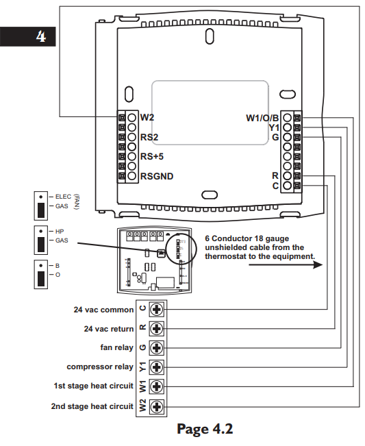
4 Wire, 1 Stage Cooling, 1 Stage Heat-Heat Pump with O reversing valve.
Residential Heat Pumps, split systems & package units, with no auxiliary heat.Venstar T1045 Programmable Thermostat fig-4

* Common wire is optional in all installations. If a common wire is not used the thermostat must be powered by two AA alkaline batteries. These batteries must be replaced (page 6) each year or when the Low Battery indicator is displayed (page 3).

5 Wire, 1 Stage Cooling, 2 Stage Heat-Heat Pump with O reversing valve.
Residential Heat Pumps, split systems & package units, with auxiliary heat.Venstar T1045 Programmable Thermostat fig-5

Common wire is optional in all installations. If a common wire is not used the thermostat must be powered by two AA alkaline batteries. These batteries must be replaced (page 6) each year or when the Low Battery indicator is displayed (page 3).

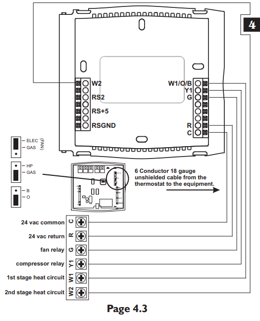
4 Wire, 1 Stage Cooling, 1 Stage Heat-Heat Pump with B reversing valve.
Residential Heat Pumps, split systems & package units, with no auxiliary heat.Venstar T1045 Programmable Thermostat fig-6

Common wire is optional in all installations. If a common wire is not used the thermostat must be powered by two AA alkaline batteries. These batteries must be replaced (page 6) each year or when the Low Battery indicator is displayed (page 3).

5 Wire, 1 Stage Cooling, 2 Stage Heat-Heat Pump with B reversing valve.
Residential Heat Pumps, split systems & package units, with auxiliary heat.Venstar T1045 Programmable Thermostat fig-7

Common wire is optional in all installations. If a common wire is not used the thermostat must be powered by two AA alkaline batteries. These batteries must be replaced (page 6) each year or when the Low Battery indicator is displayed (page 3).

Test Operation

  • Turn on the power to the Heat Pump.
  • On the thermostat, slide the Mode Switch to HEAT. Press the COOLER or WARMER button until the set temperature is 10 degrees above room temperature. The HVAC unit should energize in the heating mode.
    Note: You may need to wait up to five minutes for the heating to energize due to the compressor lockout feature. There is a two-minute minimum run-time for first-stage heating.
  • On the thermostat, slide the Aux Heat Switch to the NORMAL position. The
  • Aux Heat icon will appear indicating that the thermostat has energized Aux Heat (page 7 of the Owner’s Manual).
    TWO-STAGE OPERATION – The 2nd stage of heat (auxiliary heat) is turned on when the room temperature is equal to or less than: the setpoint minus the 1st stage deadband (one degree, adjustable), minus the 2nd stage deadband (two degrees, non-adjustable).Venstar T1045 Programmable Thermostat fig-8
  • On the thermostat, slide the Mode Switch to COOL. Press the COOLER or WARMER buttons until the set temperature is 10 degrees below room temperature. The HVAC unit should energize in the cooling mode (Page 6 of the Owner’s Manual).
    Note: You may need to wait up to five minutes for cooling to energize due to the compressor lockout feature.
  • On the thermostat, slide the Mode Switch to OFF. Slide the Fan Switch to Fan On. The fan should turn on and run continuously.

Trouble Shooting

  • SYMPTOM: The slide switches on the thermostat are very difficult to move.
  • CAUSE: The backplate of the thermostat is screwed too tightly into a wall that is not perfectly flat.
  • REMEDY: Loosen the screws holding the thermostat into the wall.
  • SYMPTOM: The Air Conditioning does not attempt to turn on.
  • CAUSE: The cooling setpoint is set too high, the Mode Switch is not set for Cool, the batteries are too weak, or the Aux Heat Switch is set for Emergency.
  • REMEDY: Consult the Normal Operation section in the Owner’s Manual to:
    • Lower the cooling setpoint.
    • Correct the Mode Switch position.
    • Replace the batteries.
    • Slide the Aux Heat Switch to Normal.
  • SYMPT OM: The fan does not turn on even though the compressor has energized.
  • CAUSE: The Fan Switch is not completely in the On or Auto position.
  • REMEDY: Slide the Fan Switch firmly into the On
  • SYMPTOM: Aux Heat does not turn on. CAUSE: The Aux Heat Switch is set for
    Lockout.
    REMEDY: Consult the Aux Heat section of this manual to slide the Aux Heat Switch to Normal (Page 7 of the Owner’s Manual).
  • SYMPTOM: The Heating does not attempt
    to turn on.
    CAUSE: The heating setpoint is set too high, the Mode Switch is not set for Heat, the batteries are too weak, or the Aux Heat Switch is set for Emergency.
  • REMEDY: Consult the Normal Operation section in this manual to:
    • Raise the heating setpoint.
    • Correct the Mode Switch position.
    • Replace the batteries.
    • Slide the Aux Switch to Normal.

Warranty

One-Year Warranty – This Product is warranted to be free from defects in material and workmanship. If it appears within one year from the date of original installation, whether or not actual use begins on that date, that the product does not meet this warranty, a new or remanufactured part, at the manufacturer’s sole option to replace any defective part, will be provided without charge for the part itself provided the defective part is returned to the distributor through a qualified servicing dealer.
THIS WARRANTY DOES NOT INCLUDE LABOR OR OTHER COSTS incurred for diagnosing, repairing, removing, installing, shipping, servicing or handling of either defective parts or replacement parts. Such costs may be covered by a separate warranty provided by the installer.
THIS WARRANTY APPLIES ONLY TO PRODUCTS IN THEIR ORIGINAL INSTALLATION LOCATION AND BECOMES VOID UPON REINSTALLATION.
LIMITATIONS OF WARRANTIES – ALL IMPLIED WARRANTIES (INCLUDING IMPLIED WARRANTIES OF FITNESS FOR A PARTICULAR PURPOSE AND MERCHANTABILITY) ARE HEREBY LIMITED IN DURATION TO THE PERIOD FOR WHICH THE LIMITED WARRANTY IS GIVEN. SOME STATES DO NOT ALLOW LIMITATIONS ON HOW LONG AN IMPLIED WARRANTY LASTS, SO THE ABOVE MAY NOT APPLY TO YOU. THE EXPRESSED WARRANTIES MADE IN THIS WARRANTY ARE EXCLUSIVE AND MAY NOT BE ALTERED, ENLARGED, OR CHANGED BY ANY DISTRIBUTOR, DEALER, OR OTHER PERSON WHATSOEVER. ALL WORK UNDER THE TERMS OF THIS WARRANTY SHALL BE PERFORMED DURING NORMAL WORKING HOURS. ALL REPLACEMENT PARTS, WHETHER NEW OR REMANUFACTURED, ASSUME AS THEIR WARRANTY PERIOD ONLY THE REMAINING TIME PERIOD OF THIS WARRANTY.
THE MANUFACTURER WILL NOT BE RESPONSIBLE FOR:

  1. Normal maintenance as outlined in the installation and servicing instructions or owner’s manual, including filter cleaning and/or replacement and lubrication.
  2. Damage or repairs are required as a consequence of faulty installation, misapplication, abuse, improper servicing, unauthorized alteration or improper operation.
  3. Failure to start due to voltage conditions, blown fuses, open circuit breakers or other damages due to the inadequacy or interruption of electrical service.
  4. Damage as a result of floods, winds, fires, lightning, accidents, corrosive environments or other conditions beyond the control of the Manufacturer.
  5. Parts not supplied or designated by the Manufacturer, or damages resulting from their use.
  6. Manufacturer products installed outside the continental U.S.A., Alaska, Hawaii, and Canada.
  7. Electricity or fuel costs or increases in electricity or fuel costs for any reason whatsoever including additional or unusual use of supplemental electric heat.
  8. ANY SPECIAL INDIRECT OR CONSEQUENTIAL PROPERTY OR COMMERCIAL DAMAGE OF ANY NATURE WHATSOEVER. Some states do not allow the exclusion of incidental or consequential damages, so the above may not apply to you.
    This warranty gives you specific legal rights and you may also have other rights which may vary from state to state.

REFERENCE:

Download Manual:   

Venstar T1045 Programmable Thermostat Installation Instructuion

Venstar-logo

Venstar T1045 Programmable Thermostat Installation Instructuion

The post Venstar T1045 Programmable Thermostat Installation Instructuion appeared first on thermostat.guide.


source https://thermostat.guide/venstar/venstar-t1045-programmable-thermostat-installation-instructuion/

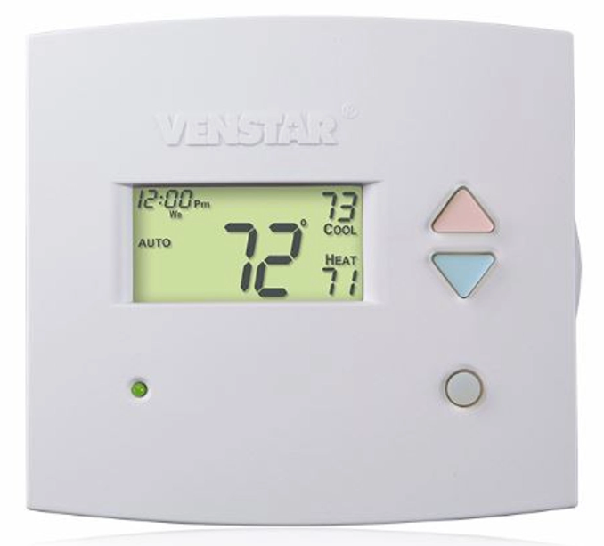
Venstar T1700 Programmable Thermostat Installation Instructuion

Venstar

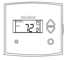
Venstar T1700 Programmable Thermostat Thermostat

Venstar-T1700-Programmable-Thermostat-Thermostat

CONFIGURABLE IN SETUP:

  • Auto or Manual changeover
  • Programmable or Non-Programmable
  • Control up to 2 Heat &
  • 1 Cool Stages
  • Backlit Display & Button
  • Legends
  • Aux Heat Indicator
  • Outdoor Sensor Ready
  • Accepts EZ Programmer
  • Accepts Optional IR
  • Remote Control
  • Accepts Comfort Call
  • Phone Control Accessory

Use with most Air Conditioning & Heating Systems including: 1 or 2 Stage Electric Cooling & 3 Stage Gas Heating, Heat Pump, Electric or Hydronic Heat.

Installation Instruction

CAUTION Follow the Installation Instructions before proceeding. Set the thermostat mode to “OFF” prior to changing settings in setup or restoring Factory Defaults.
This device complies with Part 15 of the FCC Rules. Operation is subject to the following two conditions: (1) this device may not cause harmful interference, and (2) this device must accept any interference received, including interference that may cause undesired operation.Venstar-T1700-Programmable-Thermostat-Thermostat-1

SECTION 1 Preparation

Proper installation of the thermostat will be accomplished by following these step by step instructions. If you are unsure about any of these steps, call a qualified technician for assistance.Venstar-T1700-Programmable-Thermostat-Thermostat-2

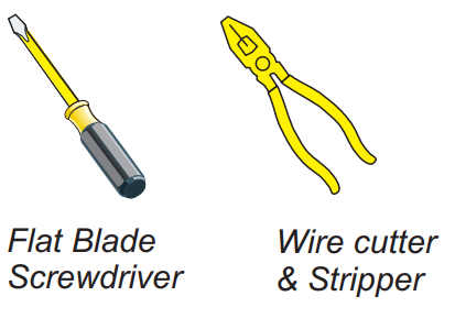
Assemble toolsVenstar-T1700-Programmable-Thermostat-Thermostat-3

  • Make sure your Heater/Air Conditioner is working properly before beginning installation of the thermostat.
  • Carefully unpack the thermostat. Save the screws, bracket, and instructions.
  • Turn off the power to the Heating/Air Conditioning system at the main fuse panel. Most residential systems have a separate breaker for disconnecting power to the furnace.

SECTION 2

Remove & Replace the Old Thermostat

  • Remove the cover of the old thermostat.
  • If it does not come off easily check for screws.
  • Loosen the screws holding the thermostat base or subbase to the wall, and lift away.
  • Disconnect the wires from the old thermostat. Tape the ends of the wires as you disconnect them, and mark them with the letter of the terminal for easy reconnection to the new thermostat.
  • Keep the old thermostat for reference purposes, until your new thermostat is functioning properly.

SECTION 3

Wire Connections
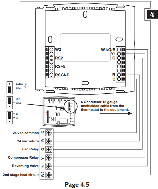
If the terminal designations on your old thermostat do not match those on the new thermostat, refer to the chart below, or the wiring diagrams that follow.Venstar-T1700-Programmable-Thermostat-Thermostat-4

Note: O/B is used if your system is a Heat Pump.

SECTION 4

Sample Wiring Diagrams
6 Wire, 1 Stage Cooling, 1 Stage Heat.

  • Residential & Commercial 1 Stage Cooling, with 1st stage Gas Heat
    OR
  • Commercial Heat Pump 1 Stage Cooling with 2 Stage HeatVenstar-T1700-Programmable-Thermostat-Thermostat-5

6 Wire, 1 Stage Cooling, 1 Stage Heat 
Residential & Commercial 1 Stage Cooling, with 1st stage Electric Heat Venstar-T1700-Programmable-Thermostat-Thermostat-6

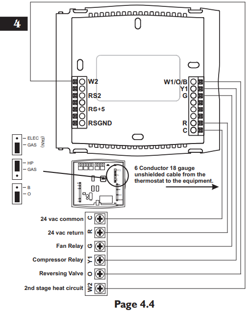
6 Wire, 1 Stage Cooling, 2 Stage Heat 
Residential Heat Pump with O Reversing Valve 1 Stage Cooling, with 2 stage Heat Venstar-T1700-Programmable-Thermostat-Thermostat-7

6 Wire, 1 Stage Cooling, 2 Stage Heat
Residential Heat Pump with b Reversing Valve 1 Stage Cooling, with 2 stage Heat Venstar-T1700-Programmable-Thermostat-Thermostat-8

Installing the Outdoor Sensor

The Outdoor Sensor measures outdoor air temperature and sends this information to the thermostat; it measures temperature with a range of -40 to 127 F.
The Outdoor Sensor should be connected to the thermostat using solid conductor CAT 5, CAT 5e, or CAT 6 type network communication cable. This is an unshielded cable with four twisted pairs of 24 gauge solid wire; DO NOT use stranded cable. The cable length should not exceed 250 feet. If less than 75 feet of cable is required to connect the thermostat to the Remote Sensor, a three conductor thermostat cable (18-24 gauge) may be used; this cable is NOT suitable for any length greater than 75 feet.
IMPORTANT: Do no use shielded wire. Do not run sensor wiring in the same conduit as the 24VAC thermostat wiring. Electrical interference may cause the sensor to give incorrect temperature readings. See the Outdoor Sensor accessory for further details.

SECTION 5 Test Operation

  • Turn the power on to the Heating/Air Conditioning system.
  • Press the MODE button repeatedly until the HEAT icon appears on the display. Press the Up or Down buttons until the set temperature is 10 degrees above room temperature. The furnace should turn on.
  • Press the MODE button repeatedly until the COOL icon appears on the display. Press the Up or Down buttons until the set temperature is 10 degrees below room temperature. The air conditioner should turn on. NOTE: Most equipment has a time delay of 5 minutes between cool cycles. This feature is defeatable on the thermostat. Consult the Owner’s Manual under Setup, cycles per hour.
  • Press the UP button until the setpoint is equal to the room temperature. Press the FAN button to Fan On. The fan should turn on and run continuously.

SECTION 6

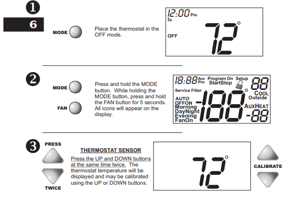
Calibrating the Thermostat Sensors
Under normal circumstances it will not be necessary to adjust the calibration of the temperature and humidity sensors. If calibration is required, please contact a trained HVAC technician to correctly perform the following procedure. Venstar-T1700-Programmable-Thermostat-Thermostat-9

SECTION 7 TroubleShooting

  • SYMPTOM: The air conditioning does not attempt to turn on.
    CAUSE: The compressor timer lockout may prevent the air conditioner from turning on, for a period of time.
     REMEDY: Consult the Owner’s Manual in the Setup section to defeat the cycles per hour and compressor timeguard.
  • SYMPTOM: The display is blank.
    CAUSE: Lack of proper power.
    REMEDY: Make sure power is turned on to the furnace and that you have 24vac between R & W. If C is used, 24vac between R & C.
  • SYMPTOM: The air conditioning does not attempt to turn on.
    CAUSE: The cooling setpoint is set too high. REMEDY: Consult the Owner’s Manual in the Setup section to lower the cooling setpoint limit.
    SYMPTOM: The heating does not attempt to turn on. CAUSE: The heating setpoint is set too low. REMEDY: Consult the Owner’s Manual in the Setup section to raise the heating setpoint limit.
  • SYMPTOM: When controlling a residential heat pump, and asking for cooling, the heat comes on.
    CAUSE: The thermostat reversing valve jumper is set for “b”.
    REMEDY: Set the reversing valve jumper for “O”. See pages 5.4 and 5.5.
  • SYMPTOM: When calling for cooling, both the heat and cool come on.
    CAUSE: The thermostat equipment jumper is configured for “HP” and the HVAC unit is a Gas/Electric.
    REMEDY: Set the equipment jumper for “Gas”. See pages 5.2 and 5.3.Venstar

Venstar T1700 Programmable Thermostat Installation Instructuion

The post Venstar T1700 Programmable Thermostat Installation Instructuion appeared first on thermostat.guide.


source https://thermostat.guide/venstar/venstar-t1700-programmable-thermostat-installation-instructuion/

Venstar T8900 Touchscreen Digital Thermostat Owner Manual

Venstar

Venstar T8900 Touchscreen Digital Thermostat 

Venstar-T8900-Touchscreen-Digital-Thermostat-Owner-Manual-product

CAUTION
Follow the Installation Instructions before proceeding. Set the thermostat mode to “OFF” prior to changing settings in setup or restoring Factory Defaults.

FCC Compliance Statement

This equipment has been tested and found to comply with the limits for an intentional radiator, pursuant to Part 15, subpart C of the FCC rules. These limits are designed to provide reasonable protection against harmful interference in a residential installation. This equipment generates, uses, and can radiate radio frequency energy and, if not installed and used in accordance with the instructions, may cause harmful interference in radio communications. However, there is no guarantee that interference will not occur in a particular installation. If this equipment does cause harmful interference to radio or television reception, which can be determined by turning the equipment off and on, the user is encouraged to try to correct the interference by one or more of the following measures:

  • • Reorient or relocate the receiving antenna.
    • Increase the separation between the equipment and receiver.
    • Connect the equipment to an outlet on a circuit different from that of the receiver.
    • Consult the dealer or an experienced radio or TV technician for help.

Notice: Only peripherals complying with FCC limits may be attached to this equipment. Operation with noncompliant peripherals or peripherals not recommended by Venstar is likely to result in interference to radio and TV reception. Changes or modifications to the product, not expressly approved by Venstar could void the user’s authority to operate the equipment.

FCC – INDOOR Mobile Radio Information
To comply with FCC/IC RF exposure limits for general population / uncontrolled exposure, the antenna(s) used for this transmitter must be installed to provide a separation distance of at least 20 cm from all persons and must not be co-located or operating in conjunction with any other antenna or transmitter. This Device complies with Industry Canada License-exempt RSS standard(s). Operation is subject to the following two conditions: 1) this device may not cause interference, and 2) this device must accept any interference, including interference that may cause undesired operation of the device.

Under Industry Canada regulations, this radio transmitter may only operate using an antenna of a type and maximum (or lesser) gain approved for the transmitter by Industry Canada. To reduce potential radio interference to other users, the antenna type and its gain should be so chosen that the equivalent isotropically radiated power (e.i.r.p.) is not more than that necessary for successful communication We, Venstar, declare under our sole responsibility that the device to which this declaration relates: Complies with Part 15 of the FCC Rules. Operation is subject to the following two conditions: (1) this device may not cause harmful interference, and (2) this device must accept any interference received, including interference that may cause undesired operation.

This color touchscreen has the ability to receive updates to its firmware. Periodically firmware updates are released by the manufacturer to add features and/or performance enhancements. This manual was produced reflecting the most current firmware/feature set at the time of publication, firmware rev. 4.04. Firmware releases after rev. 4.04 may not be adequately depicted in this manual. Please refer to the appropriate website or contact your place of purchase to learn about changes to the thermostat after firmware release 4.04.

Glossary of Terms

  • Auto-Changeover: A mode in which the thermostat will turn on the heating or cooling based on room temperature demand.
    Cool Setpoint: The warmest temperature that the space should rise to before cooling is turned on (without regard to deadband).
  • Deadband: The number of degrees the thermostat will wait, once a setpoint has been reached, before energizing heating or cooling.
    Differential: The forced temperature difference between the heat setpoint and the cool setpoint in Auto Mode.
  • Heat Setpoint: The coolest temperature that the space should drop to before heating is turned on (without regard to deadband).
  • Icon: The word or symbol that appears on the thermostat display. Mode: The current operating condition of the thermostat (i.e. Off, Heat, Cool, Auto).
  • Non-Programmable Thermostat: A thermostat that does not have the capability of running Time Period Programming.
  • Override: Changing the state from occupied to unoccupied, or from unoccupied to occupied settings.
  • Programmable Thermostat: A thermostat that has the capability of running Time Period Programming.
  • Temperature Swing: Same as Deadband.
  • Time Period Programming: A program that allows the thermostat to automatically adjust the heat setpoint and/or the cool setpoint based on the time of the day. Same as Schedule.

Get To Know Your Thermostat


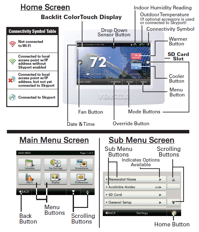
Venstar-T8900-Touchscreen-Digital-Thermostat-Owner-Manual-fig-1

Dropdown Dashboard
The Dropdown Dashboard displays temperature, humidity, and other readings. It will also show the high and low readings of the day.

Venstar-T8900-Touchscreen-Digital-Thermostat-Owner-Manual-fig-2

Care and Use of Your Thermostat
Pencils, pens and other sharp objects should never be used on your thermostat; these may damage your touchscreen. Only use your finger tip to press the touchscreen buttons.

Venstar-T8900-Touchscreen-Digital-Thermostat-Owner-Manual-fig-3

DO NOT USE ABRASIVE CLEANERS OR CLEANERS THAT CONTAIN SOLVENTS. DO NOT SPRAY ANYTHING DIRECTLY ONTO THE THERMOSTAT.

Selecting Your Desired Temperature and Mode

Venstar-T8900-Touchscreen-Digital-Thermostat-Owner-Manual-fig-4

HEAT will allow only heat operation.
COOL will allow only cool operation.
AUTO will allow both Heat and Cool operation. OFF – heating and cooling systems are turned off.Venstar-T8900-Touchscreen-Digital-Thermostat-Owner-Manual-fig-5

AUTO-CHANGEOVER MODE – Pressing the WARMER or
COOLER buttons in Auto mode will adjust both the heat and cool setpoints simultaneously. To adjust the heat and cool setpoints individually, choose HEAT mode to adjust the heat setpoint and COOL mode to adjust the cool setpoint, then return to AUTO mode.
HEAT OR COOL MODE – Pressing the WARMER or COOLER buttons in Heat or Cool mode will adjust only the heat or cool setpoints.

Using the Fan Button

Press the FAN Icon Venstar-T8900-Touchscreen-Digital-Thermostat-Owner-Manual-fig-6Venstar-T8900-Touchscreen-Digital-Thermostat-Owner-Manual-fig-7

FAN ON fan runs constantly even in OFF Mode.
FAN AUTO fan only runs with a heating or cooling demand.

Using the Override ButtonVenstar-T8900-Touchscreen-Digital-Thermostat-Owner-Manual-fig-8

Unoccupied Operation – During programmed, unoccupied periods, pressing the OVERRIDE button will force the thermostat into Occupied 1 settings. When the OVERRIDE button is pressed, a timer screen will appear and allow the user to choose from 30 minutes to up to 4 hours of override time. To turn off the override timer, press the OVERRIDE button and when the timer screen appears, press CANCEL OVERRIDE. Occupied Operation – During programmed, occupied periods, pressing the OVERRIDE button will force the thermostat into an unoccupied period for the rest of the day. During this forced unoccupied period the OVERRIDE button will operate as described above. Holiday Operation – During Holiday Mode, pressing the OVERRIDE button will force the thermostat into the Occupied 1 setting. When the OVERRIDE button is pressed, a timer screen will appear and allow the user to choose from 30 minutes to up to 4 hours of override time. To turn off the override timer, press the OVERRIDE button and when the timer screen appears, press CANCEL OVERRIDE.

Quick Start – Set Time & Date

Venstar-T8900-Touchscreen-Digital-Thermostat-Owner-Manual-fig-9

Setting the Time

Venstar-T8900-Touchscreen-Digital-Thermostat-Owner-Manual-fig-10

Setting the Date

Venstar-T8900-Touchscreen-Digital-Thermostat-Owner-Manual-fig-11

Connect to Wi-Fi (from initial start-up)
When power is connected to the thermostat and it has not been configured to connect to a Wi-Fi Access point, the following message appears:

Venstar-T8900-Touchscreen-Digital-Thermostat-Owner-Manual-fig-12

  • Select the access point you wish to connect to from the list.
  • Enter the password for the Wi-Fi Access Point and press NEXT.
  • Select automatic setup and press NEXT.
  • When finished, a dialog box will appear confirming the successful connection to the local Wi-Fi Access Point.
  • Select OK, then the Wi-Fi status page will appear. Upon closing of the Wi-Fi status page, you will be asked to join the thermostat to a Skyport account.
  • Select YES and follow the onscreen instructions to create a new Skyport account or to add the thermostat to an existing account.

Quick Start – Connect to Wi-Fi (from menus)

Venstar-T8900-Touchscreen-Digital-Thermostat-Owner-Manual-fig-13

  • Select the access point from the list that you want to connect to.
  • Enter the password for the Wi-Fi Access Point and press NEXT.
  • Select automatic setup and press NEXT.
  • When finished, a dialog box will appear confirming the successful connection to the local Wi-Fi Access Point.
  • Select OK, then the Wi-Fi status page will appear. Upon closing of the Wi-Fi status page, you will be asked to join the thermostat to a Skyport account.
  • Select YES and follow the onscreen instructions to create a new Skyport account or to add the thermostat to an existing account.

Although there is more than one way to create a Skyport account, the steps below illustrate creation from a browser. If the thermostat is connected to the local Wi-Fi Access Point, but not yet joined to a Skyport account, you may join the thermostat to an account by doing the following:

  • Select MENU from the thermostat’s home screen.
  • Scroll down
  • Select SkyportVenstar-T8900-Touchscreen-Digital-Thermostat-Owner-Manual-fig-14
  • Select Skyport Account and follow the onscreen instructions.

Skyport Account

  1. Open your browser to: https://venstar.skyportcloud.com
  2. Select “Create account now”
  3. create an Account Now
  4. Follow the on-screen instructions to create an account and add a thermostat to the Skyport account.

Main Menu Buttons – Schedule

Venstar-T8900-Touchscreen-Digital-Thermostat-Owner-Manual-fig-16Venstar-T8900-Touchscreen-Digital-Thermostat-Owner-Manual-fig-17

Main Menu Buttons – Schedule

Venstar-T8900-Touchscreen-Digital-Thermostat-Owner-Manual-fig-18

Main Menu Buttons – Fan Settings

Venstar-T8900-Touchscreen-Digital-Thermostat-Owner-Manual-fig-19Venstar-T8900-Touchscreen-Digital-Thermostat-Owner-Manual-fig-20

Main Menu Buttons – ScreensaverVenstar-T8900-Touchscreen-Digital-Thermostat-Owner-Manual-fig-23Venstar-T8900-Touchscreen-Digital-Thermostat-Owner-Manual-fig-24

Press this button to preview your screensaver operation before returning to the Home Screen. After the preview, press anywhere on the screen to return to the sub-menu.

Main Menu Buttons – Alerts

Venstar-T8900-Touchscreen-Digital-Thermostat-Owner-Manual-fig-25Venstar-T8900-Touchscreen-Digital-Thermostat-Owner-Manual-fig-26

Main Menu Buttons – Display

Venstar-T8900-Touchscreen-Digital-Thermostat-Owner-Manual-fig-27

When calibration is complete, the thermostat will automatically restart and return to the Home Screen.Venstar-T8900-Touchscreen-Digital-Thermostat-Owner-Manual-fig-28Venstar-T8900-Touchscreen-Digital-Thermostat-Owner-Manual-fig-29

Main Menu Buttons – Humidity

Venstar-T8900-Touchscreen-Digital-Thermostat-Owner-Manual-fig-30Venstar-T8900-Touchscreen-Digital-Thermostat-Owner-Manual-fig-31

Main Menu Buttons – Holidays

Venstar-T8900-Touchscreen-Digital-Thermostat-Owner-Manual-fig-32Venstar-T8900-Touchscreen-Digital-Thermostat-Owner-Manual-fig-33

Edit Holidays
Start by selecting a Holiday. You may continue to select more holidays or you can press the Repeat button for recurring holidays. Pressing a selected holiday will deselect that holiday.Venstar-T8900-Touchscreen-Digital-Thermostat-Owner-Manual-fig-34

Using the Repeat Button
Choose to repeat the holiday every week, month or year. Or, press CANCEL to go back. If you choose to repeat the holiday every week, you will be prompted to confirm the day of the week to be repeated.

Venstar-T8900-Touchscreen-Digital-Thermostat-Owner-Manual-fig-35

Using the Info Button
Press the Info button to view how non-holidays, holidays, and exceptions to repeating holidays will appear on the Holiday calendar.

Edit Holidays
Deselecting Holidays You may deselect a holiday simply by pressing on it. Press BACK to save your changes and return to the Holiday menu. If you choose to deselect a holiday that is part of a Custom Repeating Program, the screen below will appear.

Venstar-T8900-Touchscreen-Digital-Thermostat-Owner-Manual-fig-36

Marking Non-Holidays
You will now be prompted to mark this day only as a non-holiday or edit All repeating holidays that affect this day. Press SAVE to mark only this day as a non-holiday. If you choose to edit a repeating holiday that affects this day, press NEXT, and the next screen will appear.Venstar-T8900-Touchscreen-Digital-Thermostat-Owner-Manual-fig-37

Editing Repeating Holidays
If, for example, you choose to repeat the holiday every month, the following screen will appear: You may now choose to repeat the holiday:

  • On the 25th of every month
    On the 4th Monday of every month
  • On the last Monday of every month

Press SAVE to save your changes and return to Holiday programming.Venstar-T8900-Touchscreen-Digital-Thermostat-Owner-Manual-fig-38

Editing Repeating Holidays (continued)
You may now delete all repeating custom holidays in this group by pressing the ON box to uncheck your selection. Press SAVE to return to the Holiday editing screens.Venstar-T8900-Touchscreen-Digital-Thermostat-Owner-Manual-fig-39

Preset Holidays You may choose from several standard preset holidays to observe. When the preset holidays are set to ON, they will be observed every year on that date.

Overriding Holiday Mode
You may override Holiday Mode by pressing the OVERRIDE button and choosing the amount of override time desired.

Turning Off Holiday Mode From The Homescreen
You may turn off Holiday Mode by pressing the MODE button and then pressing the Holiday STOP button.Venstar-T8900-Touchscreen-Digital-Thermostat-Owner-Manual-fig-40

Main Menu Buttons – Security

Venstar-T8900-Touchscreen-Digital-Thermostat-Owner-Manual-fig-41Venstar-T8900-Touchscreen-Digital-Thermostat-Owner-Manual-fig-42

Limits on how high or low heating and cooling may be adjusted.

Main Menu Buttons – Information

Venstar-T8900-Touchscreen-Digital-Thermostat-Owner-Manual-fig-43Venstar-T8900-Touchscreen-Digital-Thermostat-Owner-Manual-fig-44

Main Menu Buttons – Settings

Venstar-T8900-Touchscreen-Digital-Thermostat-Owner-Manual-fig-45Venstar-T8900-Touchscreen-Digital-Thermostat-Owner-Manual-fig-46

Main Menu Buttons – Settings

Venstar-T8900-Touchscreen-Digital-Thermostat-Owner-Manual-fig-47Venstar-T8900-Touchscreen-Digital-Thermostat-Owner-Manual-fig-48

Main Menu Buttons – Settings

Venstar-T8900-Touchscreen-Digital-Thermostat-Owner-Manual-fig-49Venstar-T8900-Touchscreen-Digital-Thermostat-Owner-Manual-fig-50

Main Menu Buttons – Settings

Venstar-T8900-Touchscreen-Digital-Thermostat-Owner-Manual-fig-51

At 6 cycles per hour, the HVAC unit will only be allowed to energize once every 10 minutes. The Cycles Per Hour limit may be overridden and reset by pressing the WARMER or COOLER buttons. (2, 3, 4, 5, 6, No Limit)

Overview

ColorTouch thermostats support the handling of specific signals from the utility provider. The utility-generated signals carry pricing information and/or setback actions that alter the comfort settings of the thermostat in order to reduce energy usage on demand. This is known as Automated Demand Response or ADR for short. You must register to participate in a utility-sponsored program, if offered by your local utility, to take advantage of this feature.

SKYPORT CLOUD SERVICES
From the web application, the user will select Thermostat Settings from the left column. Then the Demand Response button is selected.

Venstar-T8900-Touchscreen-Digital-Thermostat-Owner-Manual-fig-52

The Demand Response configuration page, shown below, is where the thermostat is configured to respond to the energy provider’s signals. It also sets operational parameters for the thermostat. The left column of the ADR configuration page allows or prevents access by the utility. Here communication with the utility and your thermostat may be turned On or Off.
The selected utility will provide a Program ID. The Account ID would normally be the occupant’s utility account number.

Venstar-T8900-Touchscreen-Digital-Thermostat-Owner-Manual-fig-53

The right column of the ADR configuration page is where the occupant adjusts the operational parameters for ADR. The utility may send up to 3 types of ADR signals to Skyport. These are:

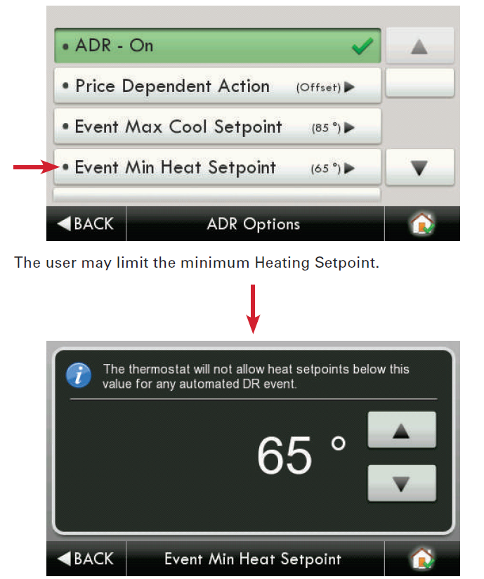
  1.  Pricing for the cost of energy, 2) An Offset to the occupants’ comfort setpoints, and 3) a signal to enforce discrete or Static setpoints. The Maximum Cooling Setpoint and Minimum Heating Setpoints for ADR events are adjusted here. The Static Settings are applied when the utility sends a signal to allow the occupant to enforce their own discrete temperature settings during an ADR event.
  2. The Offset Settings allow the utility to modify the Cool or Heat setpoints by the value set here during an ADR event. A Price Trigger setting allows the occupant to set the maximum cost of energy threshold. When this threshold is exceeded the Price dependent action is enforced. This Price Trigger and Dependent action is enforced independent of an ADR event, as long as the utility sends ‘real-time’ pricing.Venstar-T8900-Touchscreen-Digital-Thermostat-Owner-Manual-fig-54

Selecting the Overview tab of the ADR page will cause a summary of ADR events to be displayed.

Venstar-T8900-Touchscreen-Digital-Thermostat-Owner-Manual-fig-55

Automated Demand Response
Utility and Program setup must be done at the Skyport Cloud Services account. From the thermostat Home Screen, press the ‘Menu’ button, then select ‘Settings”.

Venstar-T8900-Touchscreen-Digital-Thermostat-Owner-Manual-fig-56

By selecting ADR – On, the user can participate in ADR events triggered by their utility, or price-dependent events.Venstar-T8900-Touchscreen-Digital-Thermostat-Owner-Manual-fig-57

In the above example; if the price threshold is exceeded, the thermostat will invoke the ‘Offset Setpoints’ configured for an ADR event until the event is over. Please note that the Threshold price may only be set in the Skyport Cloud Services account. Selecting ‘Skip Event’ will take no action when the set price threshold is exceeded.

Venstar-T8900-Touchscreen-Digital-Thermostat-Owner-Manual-fig-58

Main Menu Buttons – Settings

Venstar-T8900-Touchscreen-Digital-Thermostat-Owner-Manual-fig-59

Main Menu Buttons – Settings

Venstar-T8900-Touchscreen-Digital-Thermostat-Owner-Manual-fig-60

Main Menu Buttons – Settings

Venstar-T8900-Touchscreen-Digital-Thermostat-Owner-Manual-fig-62

Main Menu Buttons – Settings

Venstar-T8900-Touchscreen-Digital-Thermostat-Owner-Manual-fig-63

Main Menu Buttons – Settings
When an ADR event is pending, and hasn’t started yet, there will be a yellow leaf on the top bar. This will be accompanied by associated text as shown below.

Venstar-T8900-Touchscreen-Digital-Thermostat-Owner-Manual-fig-64

If a Warmer or Cooler button is pressed during an active ADR event, then the user is presented with this opt-out screen.Venstar-T8900-Touchscreen-Digital-Thermostat-Owner-Manual-fig-65

If a pricing-triggered ADR event is enabled, there will be a green leaf on the top bar along with the actual cost of energy. This will be accompanied by associated text as shown belowVenstar-T8900-Touchscreen-Digital-Thermostat-Owner-Manual-fig-66

Main Menu Buttons – Settings

Venstar-T8900-Touchscreen-Digital-Thermostat-Owner-Manual-fig-67

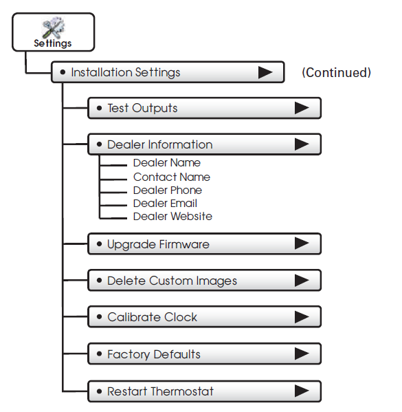
Installation Settings
The Deadband is the number of degrees or minutes that the thermostat waits before it initiates the stages of heating or cooling. 1st Stage Deadband Specifies the minimum temperature difference between the room temperature and the desired setpoint before the first stage of heating or cooling is allowed to turn on. For example, if the heat setpoint is 68˚ and the 1st Stage deadband is set to 2 degrees, the room temperature will need to drop to 66 degrees before the heat turns on.

Venstar-T8900-Touchscreen-Digital-Thermostat-Owner-Manual-fig-69

Main Menu Buttons – SettingsVenstar-T8900-Touchscreen-Digital-Thermostat-Owner-Manual-fig-70

Aux Heat will not run above this temp. (0 – 75 deg. F) The GAS/EL or HP dip switch must be set for HP and the GAS or ELEC dip switch must be set for ELEC.  Venstar-T8900-Touchscreen-Digital-Thermostat-Owner-Manual-fig-71

The AUX Output polarity may be set for Normally Open or Normally Closed to accommodate different types of humidification and dehumidification equipment.Venstar-T8900-Touchscreen-Digital-Thermostat-Owner-Manual-fig-72

IMPORTANT: Aux Output Usage must be set for Hum or Dehum before any settings will take effect in the Humidity Main Menu. Venstar-T8900-Touchscreen-Digital-Thermostat-Owner-Manual-fig-73

Dealer Information
A Dealer may enter their company contact information for the customer to use when they need service. This will appear when the “Who To Call For Service” button is pressed in the Information Menu.

Venstar-T8900-Touchscreen-Digital-Thermostat-Owner-Manual-fig-74

Main Menu Buttons – Wi-Fi

Venstar-T8900-Touchscreen-Digital-Thermostat-Owner-Manual-fig-75Venstar-T8900-Touchscreen-Digital-Thermostat-Owner-Manual-fig-76

Main Menu Buttons – Wi-Fi

Venstar-T8900-Touchscreen-Digital-Thermostat-Owner-Manual-fig-77

Main Menu Buttons – Wi-FiVenstar-T8900-Touchscreen-Digital-Thermostat-Owner-Manual-fig-78

Main Menu Buttons – Wi-FiVenstar-T8900-Touchscreen-Digital-Thermostat-Owner-Manual-fig-79

Main Menu Buttons – Skyport

Pressing this button will let you know if you are paired with a Skyport account. If not, then you may follow the prompt and instructions to create an account and add the thermostat to the account.

Main Menu Buttons – Emergency Heat

To initiate the Emergency Heat feature, Press the Emergency Heat button. During Emergency Heat operation the thermostat will turn on the fan and auxiliary stages of heat when there is a demand for heat. The 1st stage of heating and all stages of cooling will be unavailable. To exit Emergency Heat, press the Emergency Heat button.

The ColorTouch Assistant

ColorTouch Assistant may be downloaded at no charge at:

Every time the user runs the ColorTouch Assistant software, it automatically connects to the Venstar ColorTouch website in the background and updates the software and firmware
(the operating system for ColorTouch) at no cost. The ColorTouch Assistant allows you to use your computer to:

  • Upload photos for background and slideshow images
  • Program a time period schedule
  • Configure installation settings
  • Upload dealer and service contact information and company logo
  • An alternative method to updating thermostat firmware

Uploading Photos and Settings to your thermostat
When you are finished adding and editing photos and settings, click on Save to SD. When prompted, remove the SD card from the SD card reader on your computer.

At the thermostat:
Insert the SD card into the SD Card Slot.

Your thermostat will automatically save your new photos and settings in it’s internal memory. When finished, you may remove the SD card. It is not needed for normal thermostat operation.

Remove and Replace the old thermostat

To install the thermostat properly, please follow these step-by-step instructions. If you are unsure about any of these steps, call a qualified technician for assistance.

  • Assemble tools: Flat blade screwdriver, wire cutters, and wire strippers.
  • Make sure your Heater/Air Conditioner is working properly before beginning the installation of the thermostat.
  • Carefully unpack the thermostat. Save the screws, any brackets, and instructions.
  • Turn off the power to the Heating/Air Conditioning system at the main fuse panel. Most systems have a separate breaker for disconnecting power to the furnace.
  • Remove the cover of the old thermostat. If it does not come off easily, check for screws.
  • Loosen the screws holding the thermostat base or subbase to the wall and lift away.
  • If you have a smartphone handy, take a photo of the wiring for future reference.
  • Disconnect the wires from the old thermostat. Tape the ends of the wires as you disconnect them, and mark them with the letter of the terminal for easy reconnection to the new thermostat.
  • Keep the old thermostat for reference purposes, until your new thermostat is functioning properly.

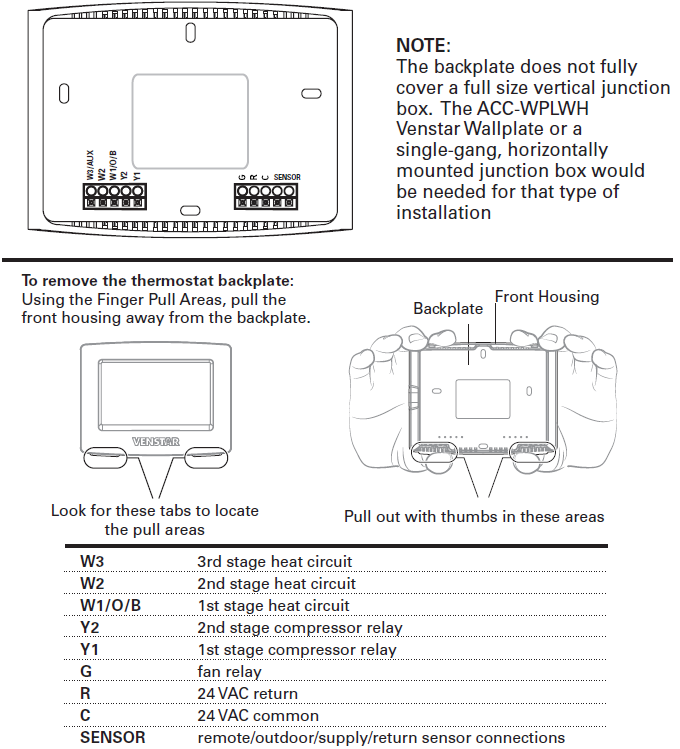
Wire Connections
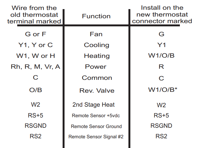
If the terminal designations on your old thermostat do not match those on the new thermostat, refer to the chart below or the wiring diagrams that follow.

Wire from the old thermostat terminal marked  

Function

Install on the new thermostat connector marked
G or F Fan G
Y1, Y Cooling Y1
W1, W Heating W1/0/B
Rh, R, M, Vr, A Power R
C Common C
O/B Rev. Valve W1/O/B*
W2 2nd Stage Heat W2
Y2 2nd Stage Cooling Y2
W3 3rd Stage Heat W3
OUT – Outdoor Sensor SENSOR
OUT + Outdoor Sensor SENSOR

O/B is used if your system is a Heat Pump. Before you go any further, determine what your existing wiring and equipment situation is.

  • If you have a Heating only system without Air Conditioning, the Venstar thermostat will require 3 wires: R (24Vac), C (24Vac) and
    W (Heat). Most systems that only have Heating use very simple thermostats that require 2 wires: the R (24Vac) and W (Heat). The Venstar thermostat requires 3 wires to the thermostat. In this case an Add-a-Wire accessory will not work and it will be necessary to install another wire for the C (24Vac) connection.
  • If you have a single-stage fossil fuel heater with air conditioning, the Venstar model will require 5 wires for independent fan control. They are R (24Vac), C (24Vac), W (Heat), Y (Cooling), and G (Fan). You may connect only 4 wires, as instructed in the “Making 4 Wires Work When 5 Wires Are Required” section on page 75.
    If there are only 4 wires present that are connected to the existing thermostat, there are at least 3 options available to connect the Venstar thermostat:
    1. Use the 4 wires as instructed in the“Making 4 Wires Work When 5 Wires Are Required” section on page 75, and note that the fan will only operate with a Heating or Cooling demand.
    2. Pull new thermostat wire from the HVAC equipment to the thermostat so that there are at least 5 wires available.
    3. Purchase and install a Venstar Add-A-Wire accessory.
  • If you have a multi-stage HVAC system comprised of a fossil fuel heater with air conditioning, the Venstar thermostat will require the 5 wires mentioned above (R, C, W, Y, G) plus an additional wire for each additional stage of Heating or Cooling. You may reduce the 5 wire requirement to 4 if you give up independent fan control following the instruction in the “Making 4 Wires Work When 5 Wires Are Required” section on page 75, or use the optional Add-A-Wire accessory.
  • if you have a heat pump without aux heat, the Venstar model will require 5 wires: R (24Vac), C (24Vac), W1/O/B (Reversing Value), Y (1st Stage Compressor), and G (Fan).
    If you are short 1 wire, there are at least 3 options available to connect the Venstar thermostat:
    1.  Use the available wires as instructed in the“Making 4 Wires Work When 5 Wires Are Required” section on page 75 and note that the fan will only operate with a Heating or Cooling demand.
    2. Pull new thermostat wire from the HVAC equipment to the thermostat so that there are at least 5 wires available.
    3. Purchase and install a Venstar Add-A-Wire accessory.
  • If you have a heat pump with aux heat, the Venstar model will require 6 wires: R (24Vac), C (24Vac), W1/O/B (Reversing Value), Y (1st Stage Compressor), W2 (Aux Heat), and G (Fan). If you are short 1 wire, there are at least 3 options available to connect the Venstar thermostat:
    1.  Use the available wires as instructed in the“Making 5 Wires Work When 6 Wires Are Required” section on page 76 and note that the fan will only operate with a Heating or Cooling demand.
    2.  Pull new thermostat wire from the HVAC equipment to the thermostat so that there are at least 6 wires available.
    3. Purchase and install a Venstar Add-A-Wire accessory.

Making 4 Wires Work When 5 Wires Are Required

If you would like to install the Venstar thermostat using only 4 wires when 5 are required, follow the directions below. You will need a screwdriver along with a 3″ long piece of thermostat wire to use as a jumper:

  1. Make sure the power is off.
  2. Label and disconnect wires at the thermostat. Please note the color and corresponding wire designator with each color. For example, The R wire is red and the W wire is white and so on. You will need this information handy for the next step at the HVAC equipment.
  3. At the HVAC equipment end of the thermostat wires (usually at the furnace), locate the terminals that the wires are attached to.
  4. Remove the “G wire” from the terminal marked G.
  5. Place the “G wire” on terminal C.
  6. Place one end of the 3″ long jumper on terminal G.
  7. Place the other end of the 3″ long jumper on terminal Y. Please note that there will be more than 1 wire on terminal Y.
  8. When connecting the wires to the Venstar thermostat, note that the wire that was previously connected to the G terminal of the old thermostat will now be required to be connected to the C terminal on the Venstar thermostat. All other wires will be connected such that the connections on each end of the individual wires match terminal designations. For example:
  9. Connect the yellow wire on the thermostat end to the Y terminal on the thermostat. The yellow wire will be connected to the Y terminal on the HVAC equipment end also.

Making 5 Wires Work When 6 Wires Are Required
If you have a system that requires 6 wires, and you would like to install the Venstar thermostat using only 5 wires, follow the directions below. You will need a screwdriver along with a 3″ long piece of thermostat wire to use as a jumper:

  1. Make sure the power is off.
  2. Label and disconnect wires at the thermostat. Please note the color and corresponding wire designator with each color. For example: The R wire is red and the W wire is white and so on. You will need this information handy for the next step at the HVAC equipment.
  3. At the HVAC equipment end of the thermostat wires (usually at the furnace), locate the terminals that the wires are attached to.
  4. Remove the “G wire” from the terminal marked G.
  5. Place the “G wire” on terminal C.
  6. Place one end of the 3″ long jumper on terminal G.
  7. Place the other end of the 3″ long jumper on terminal Y. Please note that there will be more than 1 wire on terminal Y.
  8.  When connecting the wires to the Venstar thermostat, note that the wire that was previously connected to the G terminal of the old thermostat will now be required to be connected to the C terminal on the Venstar thermostat. All other wires will be connected such that the connections on each end of the individual wires match terminal designations. For example: Connect the yellow wire on the thermostat end to the Y terminal on the thermostat. The yellow wire will be connected to the Y terminal on the HVAC equipment end also.

The Venstar ColorTouch Backplate

IMPORTANT: This thermostat requires both R (24 VAC Return) and C (24 VAC Common) be connected to the backplate terminals.

Explanation of Thermostat Dip Switches
Dip switches are located on the back of the thermostat

  • This dip switch configures the thermostat to control a conventional gas/electric system or a heat pump. If your system is anything other than a heat pump, leave this switch set for GAS/EL.**For some commercial heat pumps, this switch may need to be set for GAS/EL. Consult the commercial heat pump literature.
  • When the GAS/EL or HP dip switch is configured for HP, this dip switch (O or B) must be set to control the appropriate reversing valve. If O is chosen, the W1/O/B terminal will energize in cooling. If B is chosen, the W1/O/B terminal will energize in heating.
  1. When GAS/EL or HP is set for GAS/EL: This switch (GAS or ELEC) controls how the thermostat will control the Fan (G) terminal in heating mode. When GAS is chosen, the thermostat will not energize the Fan (G) terminal in heating. When ELEC is chosen the thermostat will energize the fan in heating.
  2. When GAS/EL or HP is set for HP: This switch (GAS or ELEC) defines the Aux Heat type. When GAS is chosen, the auxiliary heat will not be allowed to run during heat pump operation. When using a Dual Fuel system, set this switch for GAS. When ELEC is chosen, up to two stages of auxiliary strip heat will be allowed to run.

Sample Wiring Diagrams with Dip Switch
Positions Conventional Heating and Cooling Systems

Sample Wiring Diagrams with Dip Switch
Positions Heat Pump Systems

Troubleshooting

  • SYMPTOM: The thermostat touchscreen buttons are not responsive. CAUSE: The touchscreen is out of calibration.
    REMEDY: Remove the thermostat from the backplate. Push the thermostat back onto the backplate, while keeping your finger pressed firmly against the center of the touchscreen until the Calibration screen appears. Re-calibrate the touchscreen. See the Touch Calibration section of the full user’s manual (page 23).
  • SYMPTOM: The display is blank.
    CAUSE: Lack of proper power.
    REMEDY: Make sure the power is on to the HVAC and that you have 24vac between R & C.
  • SYMPTOM: The air conditioning does not attempt to turn on.
    CAUSE: The cooling setpoint is set too high.
    REMEDY: Lower the cooling setpoint or lower the cooling set-point limit. See Setpoint Limits (page 33).
  • SYMPTOM: The heating does not attempt to turn on.
    CAUSE: The heating setpoint is set too low.
    REMEDY: Raise the heating setpoint or raise the heating set-point limit. See Setpoint Limits (page 33).
  • SYMPTOM: When controlling a residential heat pump, and asking for cooling, the heat comes on.
    CAUSE: The thermostat reversing valve dip switch is set for “B”. REMEDY: Set the reversing valve jumper for “O”.
  • SYMPTOM: When calling for cooling, both the heat and cool come on. CAUSE: The thermostat equipment dip switch is configured for “HP” and the HVAC unit is a Gas/Electric.
    REMEDY: Set the equipment dip switch for “Gas”.
  • SYMPTOM: Air handler control board fuse blows when the thermostat
    is attached to the backplate with power on, but does not blow until the thermostat is placed onto the backplate.
    CAUSE: The Outdoor sensor and/or sensor wiring is shorted. REMEDY: Check/replace Outdoor sensor and/or sensor wiring.

Warranty

One-Year Warranty – This Product is warranted to be free from defects in material and workmanship. If it appears within one year from the date of original installation, whether
or not actual use begins on that date, that the product does not meet this warranty, a new or remanufactured part, at the manufacturer’s sole option to replace any defective part, will
be provided without charge for the part itself provided the defective part is returned to the distributor through a qualified servicing dealer.

THIS WARRANTY DOES NOT INCLUDE LABOR OR OTHER COSTS incurred for diagnosing, repairing, removing, installing, shipping, servicing or handling of either defective parts or replacement parts. Such costs may be covered by a separate warranty provided by the installer. THIS WARRANTY APPLIES ONLY TO PRODUCTS IN THEIR ORIGINAL INSTALLATION LOCATION AND BECOMES VOID UPON REINSTALLATION. LIMITATIONS OF WARRANTIES – ALL IMPLIED WARRANTIES (INCLUDING IMPLIED WARRANTIES OF FITNESS FOR A PARTICULAR PURPOSE AND MERCHANTABILITY) ARE HEREBY LIMITED IN DURATION TO THE PERIOD FOR WHICH THE LIMITED WARRANTY IS GIVEN. SOME STATES DO NOT ALLOW LIMITATIONS ON HOW LONG AN IMPLIED WARRANTY LASTS, SO THE ABOVE MAY NOT APPLY TO YOU. THE EXPRESSED WARRANTIES MADE IN THIS WARRANTY ARE EXCLUSIVE AND MAY NOT BE ALTERED, ENLARGED, OR CHANGED BY ANY DISTRIBUTOR, DEALER, OR OTHER PERSON WHATSOEVER. ALL WORK UNDER THE TERMS OF THIS WARRANTY SHALL BE PERFORMED DURING NORMAL WORKING HOURS. ALL REPLACEMENT PARTS, WHETHER NEW OR REMANUFACTURED, ASSUME AS THEIR WARRANTY PERIOD ONLY THE REMAINING TIME PERIOD OF THIS WARRANTY. THE MANUFACTURER WILL NOT BE RESPONSIBLE FOR:

  1. Normal maintenance as outlined in the installation and servicing instructions or owner’s manual, including filter cleaning and/or replacement and lubrication.
  2. Damage or repairs are required as a consequence of faulty installation, misapplication, abuse, improper servicing, unauthorized alteration or improper operation.
  3. Failure to start due to voltage conditions, blown fuses, open circuit breakers or other damages due to the inadequacy or interruption of electrical service.
  4. Damage as a result of floods, winds, fires, lightning, accidents, corrosive environments, or other conditions beyond the control of the Manufacturer.
  5. Parts not supplied or designated by the Manufacturer, or damages resulting from their use.
  6. Manufacturer products installed outside the continental U.S.A., Alaska, Hawaii, and Canada.
  7. Electricity or fuel costs or increases in electricity or fuel costs for any reason whatsoever including additional or unusual use of supplemental electric heat.
  8. ANY SPECIAL INDIRECT OR CONSEQUENTIAL PROPERTY OR COMMERCIAL DAMAGE
    OF ANY NATURE WHATSOEVER. Some states do not allow the exclusion of incidental or consequential damages, so the above may not apply to you. This warranty gives you specific legal rights and you may also have other rights which may vary from state to state. Patents Issued & Pending Printed on recycled paper. P/N 88-1091 Rev. 1

REFERENCE:

Download Manual:

Venstar T8900 Touchscreen Digital Thermostat Owner Manual

Venstar

Venstar T8900 Touchscreen Digital Thermostat Owner Manual

The post Venstar T8900 Touchscreen Digital Thermostat Owner Manual appeared first on thermostat.guide.


source https://thermostat.guide/venstar/venstar-t8900-touchscreen-digital-thermostat-owner-manual/

Blyss Valkla Digital Thermostat User Manual

Blyss Valkla Digital Thermostat What is in the box Check the contents of the packaging and the visual condition of the products. Contents of...